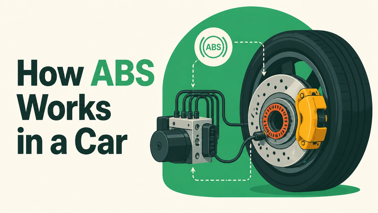
An anti-lock braking system (ABS) works in a car by continuously monitoring wheel rotational speed and automatically modulating hydraulic brake pressure up to 30 times per second when wheel lockup is detected. By preventing tires from skidding during rapid deceleration, ABS maintains tire traction, preserves steering capability, and optimizes stopping distances across most road conditions.
At a Glance
- Primary Function: Prevents wheels from locking up under heavy braking to maintain directional steering control.
- Modulating Frequency: Adjusts hydraulic brake pressure between 15 and 30 times per second via electromagnetic valves.
- Target Slip Ratio: Maintains a tire slip ratio between 10% and 20% to achieve maximum physical friction against the road.
- Disengagement Threshold: Automatically turns off below 5 to 7 mph (8 to 11 km/h) to allow the vehicle to come to a full stop.
- Pedal Feedback: Pulsing, grinding, and vibration in the brake pedal indicate normal hydraulic valve actuation, not system failure.
What are the key components of an anti-lock braking system?
An anti-lock braking system relies on four primary components working in a closed-loop electronic feedback circuit: wheel speed sensors, an Electronic Control Unit (ECU), hydraulic control valves, and a hydraulic pump. Each part performs a dedicated monitoring, processing, or mechanical control function to manage hydraulic brake pressure.
+--------------------------+
|  Wheel Speed Sensor      | ---> Reads rotational RPM (100+ times/sec)
+--------------------------+
             |
             v
+--------------------------+
| Electronic Control Unit  | ---> Analyzes deceleration rates & calculates slip
+--------------------------+
             |
             v
+--------------------------+
| Hydraulic Control Unit   | ---> Opens/closes valves & runs motor pump
+--------------------------+
             |
             v
+--------------------------+
| Brake Caliper / Pad      | ---> Modulates clamping force on brake rotor
+--------------------------+
- Wheel Speed Sensors: Mounted on the wheel hubs, these reluctance or Hall-effect sensors read tone rings to monitor rotational speed. They transmit speed updates to the ECU over 100 times per second.
- Electronic Control Unit (ECU): The central computer processes incoming speed signals, calculates instantaneous wheel deceleration, compares individual wheel speeds, and commands the hydraulic unit.
- Hydraulic Control Unit (HCU) Valves: Solenoid valves placed inside the hydraulic brake lines control line pressure. Position 1 allows full master cylinder pressure through; Position 2 blocks line pressure; Position 3 vents pressure back to a reservoir.
- Hydraulic Pump and Motor: When valves vent pressure to prevent wheel lockup, the electric pump motor pushes fluid back into the hydraulic lines, restoring system pressure for the next braking pulse.
How does the ABS cycle modulate hydraulic brake pressure step-by-step?
The ABS cycle operates through a four-stage loop consisting of monitoring, lockup detection, pressure release, and pressure re-application. This continuous cycle repeats up to 30 times every second for each affected wheel until the driver releases the brake pedal or traction is restored.
- Continuous Monitoring: As the driver depresses the brake pedal, fluid flows from the master cylinder directly to the brake calipers. The wheel speed sensors continuously send frequency signals to the ECU.
- Lockup Detection: When the driver applies extreme pedal pressure, tire friction drops and a wheel rapidly decelerates at a rate far exceeding physical vehicle stopping capability (indicating imminent wheel lockup).
- Pressure Release: The ECU instantly energizes the solenoid valve for that specific wheel to the vent position. This isolates the master cylinder and releases hydraulic fluid into an accumulator reservoir, allowing the wheel to resume rotation.
- Pressure Re-application: Once the sensor shows the wheel acceleration returning to a safe rotational threshold, the ECU switches the valve position and runs the hydraulic pump. The pump forces high-pressure fluid back into the caliper line, applying clamping force again.
What target wheel slip ratio produces maximum braking grip?
An anti-lock braking system targets a wheel slip ratio between 10% and 20% to maximize longitudinal friction force between the tire rubber and the road surface. A 0% slip ratio indicates a free-rolling wheel with zero braking force, whereas a 100% slip ratio defines a completely locked tire skidding across the pavement.
   Braking Force
       ^
  MAX |       /---\  <--- Peak Grip Zone (10% to 20% Slip Ratio)
      |      /     \
      |     /       \________  <--- Locked Wheel / Pure Skid (100% Slip)
      |    /
      +-------------------------> Wheel Slip Ratio (%)
          0%    15%       100%
Tire friction dynamics dictate that rubber generates its highest coefficient of kinetic friction when it is slipping slightly against the road rather than rolling completely free or sliding passively. Within the 10% to 20% window, the tire treads deform slightly, digging into micro-irregularities in the asphalt.
If wheel slip exceeds 20%, directional stability drops sharply, lateral cornering force plummets to near zero, and stopping distance increases. The ECU calculates real-time slip ratio by comparing vehicle body speed (derived from all four wheels) against individual wheel rotational speeds, constantly modulating line pressure to hold tire behavior in this optimal 15% window.
How do 1-channel, 3-channel, and 4-channel ABS setups differ?
ABS setups differ in their number of speed sensors and independent hydraulic control valves, ranging from older 1-channel systems to modern 4-channel architectures. The number of channels determines whether wheels are controlled individually or in groups.
| System Type | Sensor Configuration | Hydraulic Valve Channels | Operating Logic & Vehicle Applications |
| 1-Channel, 1-Sensor | 1 sensor on the rear axle differential | 1 valve controlling both rear brakes together | Used on older light trucks. Prevents rear-end swing out, but cannot prevent front wheel lockup or adjust left/right rear distribution. |
| 3-Channel, 3-Sensor | 2 sensors on front wheels, 1 sensor on rear axle | 2 independent front valves, 1 shared rear valve | Common on 1990s passenger cars. Controls front wheels individually for steering, while both rear wheels modulate together using Select-Low logic. |
| 4-Channel, 4-Sensor | 4 sensors (one at every wheel hub) | 4 independent hydraulic valves | Modern global standard. Monitors and regulates braking force at every corner independently, maximizing stability, short stops, and cornering grip. |
At what exact speed threshold does ABS disengage, and why?
ABS automatically turns off at vehicle speeds below 5 to 7 mph (8 to 11 km/h) because mathematical logic breaks down as wheel rotational speed approaches zero. If the ECU attempted to eliminate 100% of wheel slip at 1 mph, it would interpret the natural stopping of the wheel as an unwanted lockup event and repeatedly release pressure, making it physically impossible to bring the car to a complete stop.
By setting a hard cut-off threshold at low speeds, automobile engineers ensure that traditional mechanical friction takes over during final braking. Drivers can securely hold the vehicle stationary at stoplights, parking spaces, and steep inclines without computer interference.
How does ABS handle split-mu surfaces like ice next to dry asphalt?
On split-mu (split-friction) surfaces where the left side of the vehicle rests on low-friction ice and the right side rests on high-friction dry asphalt, ABS uses Select-Low or Yawning Control algorithms to balance stopping power against directional stability.
If the ECU permitted full brake pressure on the right tires while releasing pressure on the left tires, the massive asymmetric drag force would create a sharp yawing moment, spinning the vehicle around violently toward the dry pavement side. To prevent driver loss of control, the ECU limits hydraulic pressure on the high-grip side initially, gradually ramping up pressure while the driver or electronic steering systems apply counter-steering force.
While this Select-Low strategy slightly increases overall stopping distance on split-mu surfaces, it guarantees absolute vehicle yaw stability and prevents catastrophic loss of control.
Why does ABS increase stopping distance on loose gravel, sand, and deep snow?
ABS increases stopping distance on loose surfaces like gravel, unpaved dirt, sand, and deep snow because preventing wheel lockup prevents tires from digging into the sub-layer of the road.
When a non-ABS wheel locks up on loose terrain, the skidding tire acts like a wedge or plow. It pushes uncompacted gravel or snow forward, building up a large physical embankment in front of the tire tread that rapidly decelerates the vehicle.
Non-ABS (Locked Wheel):
   [ Direction of Travel ---> ]
          ( TIRE ) ===> Plowing Effect
         /        \
   ======  Loose Gravel Wedge  ====== (Car stops rapidly)

ABS Active (Rolling Wheel):
   [ Direction of Travel ---> ]
          ( TIRE ) ---> Rolling Motion
         ~~~~~~~~~~
   ================================== (Car rolls over gravel, extending stop distance)
Because ABS releases brake pressure whenever it detects tire lockup, the system forces the tire to roll continuously over the loose surface layer instead of plowing into it. On unpaved gravel roads, an ABS-equipped vehicle can experience stopping distance increases between 20% and 50% compared to a vehicle with locked wheels.
Why does braking on corrugated washboard roads trigger false ABS activation?
Braking on washboard roads, severe potholes, or expansion joints triggers false ABS activation because suspension bounce causes tires to temporarily catch air and lose physical contact with the ground.
When a tire bounces off the road surface while the brake pedal is depressed, line pressure stops the unweighted wheel instantly in mid-air. The ECU detects a rapid RPM drop to zero and misinterprets the unweighted airborne state as a severe locked-wheel skid.
The system immediately opens hydraulic solenoid valves to vent line pressure. When the tire lands back on the pavement a split-second later, the driver feels a momentary loss of braking pressure and pedal shudder as the system attempts to restore hydraulic clamping force to an unweighted wheel.
How do mismatched tire diameters or uneven tread wear disrupt ABS sensors?
Mismatched tire diameters, space-saver spare tires, or significantly uneven tread wear disrupt ABS operation by altering the wheel rolling radius and changing sensor pulse frequencies.
Wheel speed sensors read rotational speed based on total wheel revolutions per mile. A tire with reduced outer diameter (such as a compact spare tire or a tire worn down by 6/32 inches relative to new tires) must rotate faster to cover the exact same road distance.
- False ECU Calibration: The ECU reads the higher pulse frequency from the smaller tire and detects a permanent speed discrepancy between wheels.
- Nuisance Interventions: The ECU may misinterpret natural rotational speed variance during straight-line driving as a loss of traction, triggering unwanted valve cycling.
- System Deactivation: If the rotational speed variance exceeds programmed safety tolerance windows (typically 3% to 5%), the ECU flags a fault code, illuminates the dashboard warning light, and completely disables ABS functionality.
How does ABS interface with Electronic Stability Control (ESC) and Traction Control?
ABS forms the foundational hydraulic and sensor hardware layer for both Electronic Stability Control (ESC) and Traction Control Systems (TCS). While baseline ABS activates only during driver-initiated braking, ESC and TCS utilize the exact same sensors, pump, and valve solenoids to automatically apply brakes without driver pedal input.
                     +---------------------------+
                     | Wheel Speed Sensors & HCU |
                     +---------------------------+
                                   |
         +-------------------------+-------------------------+
         |                         |                         |
         v                         v                         v
  [ ABS System ]           [ Traction Control ]      [ Electronic Stability ]
  Prevents wheel lockup    Prevents wheel spin       Corrects oversteer/understeer
  during manual braking    during acceleration       via selective wheel braking
- Traction Control System (TCS): TCS works during vehicle acceleration. If a wheel spins freely on ice while accelerating, TCS commands the ABS pump to apply brake force to that single wheel, transferring drive torque across the open differential to the gripping tire.
- Electronic Stability Control (ESC): ESC monitors steering wheel angle, lateral acceleration, and vehicle yaw sensors. If it detects understeer (plowing straight) or oversteer (tail-sliding), ESC selectively fires individual ABS wheel valves to drag specific corner tires, generating correcting yaw torque to stabilize the vehicle.
Why does the brake pedal vibrate and grind when ABS activates?
The brake pedal vibrates, shudders, and produces a mechanical grinding noise during hard braking because the hydraulic pump motor is forcing brake fluid back against pedal force while solenoid valves cycle rapidly open and closed.
When ABS engages:
- Hydraulic pressure valves open and close at frequencies up to 30 Hz.
- Fluid vented into internal accumulators must be purged.
- The electric hydraulic pump motor kicks on, pressurizing fluid back toward the master cylinder.
This rapid backpressure pulsing pushes directly against the driver’s foot on the brake pedal. The grinding noise is the mechanical combination of valve solenoids clicking, the electric pump motor running under load, and rapid pad-to-rotor pulsing. This feedback indicates normal, active operation.
Should you pump the brakes manually in a vehicle equipped with ABS?
No, you must never pump the brakes manually in a vehicle equipped with an anti-lock braking system. Manually pumping the brake pedal releases line pressure, defeats system electronics, and dramatically increases total stopping distance.
When a driver pumps the pedal, they cycle hydraulic pressure 1 to 2 times per second at best, while completely interrupting the ECU’s ability to analyze traction conditions. In an emergency in an ABS-equipped vehicle, the driver must perform “stomp and steer” braking: apply immediate, maximum continuous pressure to the brake pedal and hold it down firmly while steering around hazards. The computer handles fluid modulation at optimal efficiency.
How does ABS enable directional steering during emergency braking?
ABS enables directional steering during panic stops because rolling tires generate lateral (side-to-side) cornering friction, whereas skidding tires generate zero cornering friction.
Physics dictates that friction force operates along a directional vector. When a tire locks completely (100% slip ratio), all available tire-to-road friction goes toward sliding forward down the vehicle’s momentum line. Turning the steering wheel changes the physical orientation of the front tires, but because a sliding tire has no lateral grip reserve, the vehicle continues sliding straight ahead regardless of steering wheel angle.
By cycling pressure to keep the front tires rotating at a 15% slip ratio, ABS maintains a reserve of lateral traction. This lateral traction allows steering inputs to transfer force against the road, allowing the driver to steer around obstacles while maintaining full braking deceleration.
What happens to vehicle braking when the ABS warning light turns on?
When the ABS warning light turns on, the ECU has identified an internal system fault, logged a Diagnostic Trouble Code (DTC), and completely deactivated anti-lock modulation functions.
When the system deactivates:
- Standard Hydraulic Braking Remains Operational: The primary hydraulic brake lines, master cylinder, vacuum booster, calipers, and pads continue working as normal mechanical brakes.
- Loss of Anti-Lock Capability: Under hard emergency braking or on slick surfaces, pushing the pedal too far will cause the wheels to lock up, skid, and lose steering capability.
- Electronic Brake Distribution (EBD) Loss: On many modern vehicles, a secondary red brake warning light accompanying the amber ABS light indicates that Electronic Brake Distribution is also disabled, increasing the risk of premature rear-wheel lockup during moderate stops.
What are the most common mechanical and electrical failure points in ABS?
ABS reliability relies on precise electrical resistances and hydraulic sealing. System failures typically stem from five key components across wheel ends, wiring, and fluid circuits.
- Wheel Speed Sensor Failure: Exposed to harsh road debris, road salt, and heat, wheel speed sensor pickup coils break internally or accumulate metal shavings on magnetic tips, disrupting pulse signals.
- Corroded or Cracked Tone Rings: Reluctance system tone rings mounted on CV axle shafts rust, split, or clog with mud, presenting uneven gear teeth intervals to speed sensors.
- Hydraulic Control Unit Valve Seizure: Moisture build-up in contaminated brake fluid causes internal hydraulic solenoid valve spools to corrode and stick in open or closed positions.
- Blown ABS Pump Motor Relays: High electrical current draws during frequent system cycling can pit electrical contacts or blow dedicated high-amperage fuses/relays supplying the hydraulic pump motor.
- Damaged Wiring Harnesses: Wheel hub wiring harnesses experience constant suspension flexing, leading to internal wire breakage, insulation chafing, or water intrusion in sensor connectors.
The Bottom Line
An anti-lock braking system uses speed sensors, an ECU, and hydraulic valves to modulate brake pressure up to 30 times per second, keeping tire slip within an optimal 10% to 20% traction range. This process prevents wheel lockup and preserves driver steering control during panic stops.
While ABS significantly shortens stopping distances on wet pavement and asphalt, it can extend stopping distances on loose surfaces like deep snow or unpaved gravel. During emergency stops, drivers should maintain steady, firm pedal pressure and steer, ignoring pedal vibration and mechanical pump noise as the system operates.