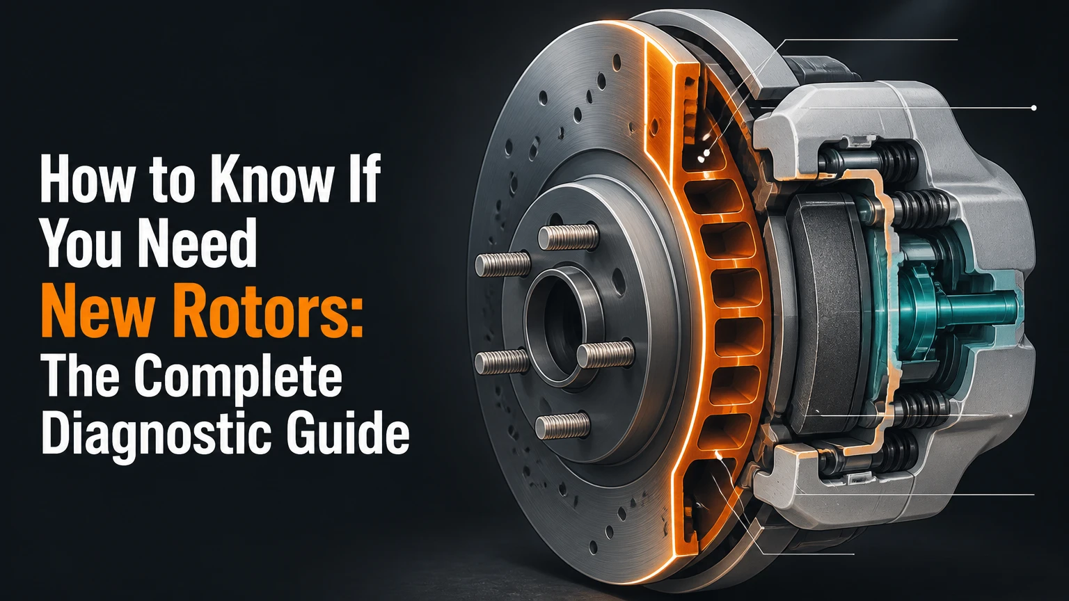
Determining whether your brake rotors require replacement requires measuring three distinct physical parameters: minimum discard thickness, parallelism variation, and lateral runout. By systematically inspecting the rotor surface under load and using precision measuring tools across 6 procedural steps, you can accurately diagnose rotor health in 45 to 70 minutes. Performing this check prevents premature brake pad destruction, eliminates pedal pulsation, and maintains safe stopping distances.
Before You Start
- Total Time Required: 45 to 70 minutes per axle.
- Difficulty Level: Intermediate (requires basic jacking safety and precision measurement).
- Estimated Cost: $0 (DIY inspection with existing tools) or $30 to $60 (tool rental/purchase).
- Prerequisites: Vehicle parked on a level concrete surface with engine off and transmission in gear or Park.
Tool and Material Checklist
| Item | Purpose | Exact Spec / Quantity |
| Floor Jack & Jack Stands | Elevate and lock vehicle safely | 1 hydraulic floor jack, 2 jack stands (rated for vehicle gross weight) |
| Wheel Chocks | Prevent opposite axle movement | 2 heavy-duty rubber chocks |
| Digital Micrometer | Measure friction surface thickness | 1 micrometer with pointed anvils ($0.001\text{ mm}$ precision) |
| Dial Indicator Kit | Test lateral rotor warping | 1 dial gauge ($0.01\text{ mm}$ resolution) with flexible magnetic arm |
| Brake Cleaner | Degrease rotor faces | 1 can aerosol brake cleaner |
| Wire Brush / Hub Cleaner | Scrape rust scale off hub face | 1 stiff steel wire brush or drill attachment |
| Torque Wrench | Tighten lug nuts accurately | 1 drive torque wrench ($10\text{ to }150\text{ lb-ft}$ range) |
| Vehicle Service Manual | Identify factory discard limits | 1 manual or official repair database |
Step-by-Step Inspection Process
Step 1: Isolate Symptoms and Prepare the Vehicle Setup
Park your vehicle on flat concrete, engage the parking brake, and place wheel chocks behind the rear tires if working on the front axle. Identify the vibration source: steering wheel wobble during braking indicates front rotor issues, while pedal pulsation without steering movement points to rear rotor defects. Loosen the lug nuts on the target wheel by one-half turn using a lug wrench while the tire remains firmly on the ground. Place the floor jack beneath the manufacturer-designated frame jacking point, elevate the vehicle, and position a jack stand directly under the structural frame rail. Lower the vehicle onto the jack stand, remove the lug nuts completely, and pull the wheel off the hub.
Success Checkpoint: You will know the setup is successful when the vehicle sits solidly on the jack stand with zero rocking movement when pushed firmly at the fender.
Common Mistake: Lifting the vehicle without breaking the initial lug nut torque while on the ground. Attempting this while suspended on a jack stand causes dangerous vehicle instability. Always break lug nut resistance on the ground first.
Step 2: Clean and Perform Visual Surface Audit
Spray the front and rear rotor faces liberally with aerosol brake cleaner and wipe the surfaces clean using a lint-free shop rag. Inspect the friction surface under bright lighting, searching for deep concentric grooves, a raised outer edge lip, heat cracks, or dark blue spots indicating extreme thermal stress. Slide your fingernail vertically from the center hat outward across the pad contact path. If your fingernail catches in deep scoring grooves or hits a severe ridge at the outer edge, the surface is heavily worn.
Success Checkpoint: You will know it worked when the rotor face is completely degreased and free from loose brake dust, allowing clear visibility of metal discoloration and groove depth.
Common Mistake: Confusing light, orange surface rust with structural failure. Flash rust forms within hours of rain or car washes and wipes off during normal braking. Dark blue spots or deep scoring that catches a fingernail are the true indicators of structural wear.
Step 3: Measure Minimum Discard Thickness Across Pad Sweep Path
Locate the stamped minimum thickness specification (often abbreviated as “Min Thk”) on the rotor hat or outer cooling vane rim. Open your digital micrometer and position its measuring anvils $10\text{ mm}$ inward from the outer edge to bypass any non-contact rust lip. Record the exact measurement in millimeters or inches. Move the micrometer to 8 equally spaced locations around the circumference of the rotor, taking care to stay within the middle of the pad contact path.
$$\text{Discard Condition} = \text{Measured Thickness} \le \text{Stamped Minimum Thickness}$$
If any single measurement point reads equal to or less than the stamped minimum thickness spec, the rotor cannot be saved and must be replaced immediately.
Success Checkpoint: You will know it worked when you have logged 8 clean thickness readings taken from the active friction zone, all positioned clear of outer rust ridges.
Common Mistake: Using standard flat-jaw digital calipers instead of a micrometer. Caliper jaws bridge over the raised outer rust lip, delivering a false reading that makes worn rotors appear thicker than they actually are.
Step 4: Calculate Thickness Variation Across Circumference
Review the 8 thickness measurements recorded in Step 3 and identify the highest and lowest values. Calculate Disc Thickness Variation (DTV), also known as parallelism loss, using the following formula:
$$\text{DTV} = \text{Thickness}_{\max} – \text{Thickness}_{\min}$$
Compare your calculated variation against the industry maximum limit of $0.013\text{ mm}$ ($0.0005\text{ inches}$). If your maximum measurement is $24.420\text{ mm}$ and your minimum measurement is $24.395\text{ mm}$, the variation equals $0.025\text{ mm}$. Because $0.025\text{ mm}$ exceeds the $0.013\text{ mm}$ tolerance, the rotor suffers from parallelism loss and will cause brake pedal pulsation.
Success Checkpoint: You will know it worked when you have subtracted the absolute lowest measurement from the highest measurement to confirm whether variation stays under $0.013\text{ mm}$.
Common Mistake: Taking measurements at only one location on the rotor. Parallelism loss occurs unevenly around the disc, meaning a rotor can pass thickness testing at 12 o’clock while failing miserably at 4 o’clock.
Step 5: Measure Lateral Runout with Dial Indicator
Thread 3 lug nuts onto the wheel studs by hand and snug them tightly against the rotor hat using stacked washers. This clamps the rotor flat against the wheel hub face, reproducing real wheel mounting force. Mount the magnetic base or clamping arm of your dial indicator to a rigid suspension component, such as the steering knuckle or lower control arm. Position the indicator tip perpendicular to the rotor face, roughly $10\text{ mm}$ inside the outer edge, and preload the gauge stem by pressing it in $1.0\text{ mm}$ before zeroing the dial bezel. Slowly turn the rotor by hand through one full $360^\circ$ rotation while watching the indicator needle.
$$\text{Lateral Runout} = \text{Maximum Gauge Deviation} \le 0.05\text{ mm}$$
If the total needle sweep exceeds $0.05\text{ mm}$ ($0.002\text{ inches}$), the rotor has unacceptable lateral runout and must be resurfaced or replaced.
Success Checkpoint: You will know it worked when the rotor turns a full $360^\circ$ while the dial indicator tip stays in continuous contact with the smooth metal face, giving a clear continuous reading.
Common Mistake: Testing lateral runout without securing the rotor to the hub with lug nuts. An unbolted rotor floats loosely on the studs, creating false runout readings over $0.20\text{ mm}$.
Step 6: Clean Hub Mating Face and Torque Lug Nuts to Spec
Remove the dial indicator and lug nuts, then pull the rotor off the hub studs. Scrape all rust, scale, and corrosion off the flat mating face of the wheel hub using a wire brush or hub cleaning drill bit until bare, shiny metal is exposed. Spray the area with brake cleaner and reinstall the rotor. Remount the wheel and hand-tighten all lug nuts in a star pattern. Lower the vehicle until the tire rests lightly on the ground to prevent spinning. Set your torque wrench to the manufacturer specification (typically $80\text{ to }100\text{ lb-ft}$) and torque each lug nut in a crisscross star pattern. Lower the vehicle completely and remove the wheel chocks.
Success Checkpoint: You will know it worked when every lug nut produces an audible click from the torque wrench set to factory specification, and the wheel rotates smoothly without wobble.
Common Mistake: Tightening lug nuts with an uncalibrated pneumatic impact gun. Uneven lug nut clamping force warps the brake rotor hat instantly, causing severe pedal vibration within 1,000 miles.
Common Mistakes and How to Fix Them
1. High Runout Reading on a Brand-New Rotor
- The Failure: You install a brand-new replacement rotor, but the dial indicator measures $0.08\text{ mm}$ of lateral runout, exceeding the $0.05\text{ mm}$ tolerance limit.
- The Fix: Remove the rotor and inspect the underlying wheel hub face. Rust scale or debris sandwiched between the hub and rotor hat cocks the rotor at a slight angle. Scrub the hub face with a wire wheel until it is completely flat bare metal, wipe with brake cleaner, and re-test.
2. Stripping the Rotor Retaining Screw
- The Failure: The countersunk Phillips screw securing the rotor hat to the hub strips its head when you attempt to loosen it with a standard screwdriver.
- The Fix: Do not keep turning with a manual screwdriver. Spray penetrating oil behind the screw head, place a manual impact driver fitted with a #3 Phillips bit into the screw slot, and strike the back of the impact driver firmly with a 3-pound brass hammer to break rust bonds instantly.
3. False Measurements Caused by Measuring Over the Outer Lip
- The Failure: Your micrometer reads well above minimum thickness, but visual inspection shows thin, worn metal inside the pad track.
- The Fix: The micrometer anvil was placed over the unworn outer rust ridge. Move the micrometer anvils $10\text{ mm}$ inward into the sunken pad contact path to take your reading.
4. Ignoring Pad Material Transfer (Pseudo-Warping)
- The Failure: The brake pedal pulses violently, but both thickness variation and runout readings measure well within factory limits.
- The Fix: Severe heat causes brake pad friction material to weld unevenly onto the rotor face in microscopic patches. Clean the rotor face using medium-grit ($120\text{-grit}$) sandpaper attached to an orbital sander or block to remove sticky pad deposits, then re-bed the brakes.
Inspection Variations
Situation A: Inspecting Solid vs. Ventilated Rotors
Solid rotors (commonly found on rear axles or compact cars) consist of a single solid metal plate, whereas ventilated rotors feature internal cooling vanes sandwiched between two friction faces.
- Solid Rotors: Solid discs wear thin rapidly and have narrower safety tolerances. Measure thickness near the center of the pad area, as solid discs tend to dish inward under heat.
- Ventilated Rotors: Check the internal cooling vents for structural rust flaking or blockage. Heavy rust scaling inside the inner cooling vanes reduces heat dissipation, causing rapid thermal distortion even if surface thickness passes inspection.
Situation B: Inspecting Rotors Without Specialty Precision Tools
If you do not own a digital micrometer or dial indicator kit, you can perform an initial field triage before visiting an auto parts shop:
- Fingernail Test: Run your fingernail from the center of the rotor hat outward to the lip. A drop depth greater than $1.0\text{ mm}$ indicates that the rotor has reached the end of its service life.
- Flashlight Reflection Check: Shine a bright light at an angle across the disc face. Blue/purple concentric rings or dark spots indicate thermal hotspots that have altered the grain structure of the cast iron, requiring full replacement.
How Long Does It Take and What Does It Cost?
Doing this inspection yourself saves substantial labor costs while ensuring accurate diagnostics.
| Diagnostic Method | Time Investment | Equipment Cost | Professional Service Cost |
| DIY Inspection (Standard Tools) | 45 to 70 minutes per axle | $0 (if equipment owned) | N/A |
| DIY Precision Tool Purchase | 45 to 70 minutes per axle | $35 to $65 (Micrometer + Dial Gauge) | N/A |
| Professional Shop Diagnostic | 1 to 2 hours (shop turnaround) | N/A | $80 to $150 (often waived if repaired) |
Frequently Asked Questions
Can I replace brake pads without replacing or turning the rotors?
You can replace pads without replacing rotors only if the current rotors exceed minimum discard thickness by at least $0.76\text{ mm}$, show less than $0.013\text{ mm}$ thickness variation, and have no deep scoring. Installing new flat pads onto grooved or uneven rotors reduces stopping power and causes rapid pad wear.
Should rotors be replaced in pairs?
Yes, brake rotors must always be replaced in pairs across the same axle. Installing a new rotor on one side while leaving a worn rotor on the opposite side creates uneven braking force, causing the vehicle to pull dangerously toward one side during emergency hard stops.
What is the difference between turning rotors and replacing them?
Turning (resurfacing) rotors involves mounting them on a precision brake lathe to cut away a thin layer of metal, restoring a flat surface. Replacement involves installing brand-new cast iron rotors. Turning is only viable if remaining thickness after machining remains well above factory minimum discard specs.
Why do my new rotors shake when I step on the brake pedal?
New rotors shake if the wheel hub face was not cleaned down to bare metal prior to installation, or if lug nuts were tightened unevenly without a torque wrench. Debris behind the rotor hat or improper torque causes excessive lateral runout, producing instant pedal vibration.
How many miles do brake rotors typically last?
Brake rotors generally last between 30,000 and 70,000 miles depending on driving habits, vehicle weight, pad material, and climate. City driving with frequent stops and exposure to road salt significantly accelerates rust buildup and rotor wear compared to smooth highway driving.