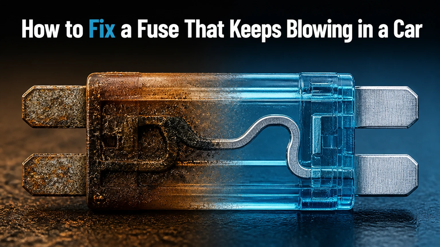
A blown fuse in a vehicle is a symptom, not the root cause. When a fuse repeatedly blows the moment you replace it or operate a specific circuit, an underlying electrical fault is actively pulling excessive current to protect the wiring harness from melting or catching fire. Replacing a blown fuse with a new one without locating this fault will only result in another popped fuse. Fixing a fuse that keeps blowing requires locating and repairing a short circuit to ground or an internally shorted electrical component. Following a structured electrical diagnostic process allows you to isolate the defect, perform a permanent repair, and restore the circuit to full operation.
Before You Start
- Time Required: 1 to 2 hours
- Difficulty Level: Intermediate
- Estimated Cost: $10 – $35 (assuming basic tools are on hand)
- Prerequisite Conditions: Vehicle parked on a flat surface, engine off, ignition key removed, and parking brake engaged.
Tools and Materials Checklist
- Digital Multimeter (DMM): 1 unit (capable of measuring DC Volts and Resistance/Continuity)
- 12V Automotive Test Light: 1 unit (recommended for non-destructive visual short testing)
- Automotive Resetting Circuit Breaker: 1 unit (matching the target fuse footprint and amperage; optional but prevents wasting standard fuses)
- Replacement Fuses: 3 to 5 units (matching the exact OEM amperage rating and blade style: ATO, Mini, or Low-Profile Mini)
- Fuse Puller Tool or Needle-Nose Pliers: 1 unit
- Vehicle Owner’s Manual / Wiring Diagram: 1 copy (for fuse panel layouts and shared circuit maps)
- Wire Stripper / Crimper Tool: 1 unit
- Heat Shrink Tubing or Liquid Electrical Tape: 1 package
- Electrical Tape: 1 roll (high-temperature automotive grade)
- Non-Conductive Trim Removal Tools: 1 set (for accessing hidden wiring looms under interior trim)
Step-by-Step Diagnostic and Repair Process
[Vehicle Safety Prep] ➔ [Map Socket Terminals] ➔ [Setup Non-Destructive Test]
│
[Verify Operational Circuit] [Repair Component/Wire] [Isolate Faulty Branch]
Step 1: Perform Safety Preparation and Access the Fuse Panel
Turn off the ignition completely, remove the key fob from proximity range, set the parking brake, and disconnect the negative battery cable using a 10mm wrench.
Consult your owner’s manual to locate the specific fuse box controlling the dead circuit. Vehicles contain multiple fuse blocks: one under the dashboard on the driver or passenger side, one under the hood near the battery, and occasionally a third in the trunk or rear cargo area. Unclip the fuse box cover and reference the diagram printed on the inside of the lid to find the specific slot number and name (e.g., “CIGAR / AUX 15A” or “TAIL LT 10A”).
Use a dedicated plastic fuse puller or needle-nose pliers to extract the blown fuse straight out of its socket. Inspect the translucent plastic housing. A visibly severed metal strip or black carbon soot confirms the fuse blew from overcurrent.
Success Checkpoint: You have safely extracted the correct blown fuse, identified its designated slot number, and confirmed a broken internal element.
Common Mistake: Prying fuses out at an angle with metal screwdrivers. This can crush the plastic socket terminals or short adjacent live pins together. Pull straight upward with non-conductive plastic tools.
Step 2: Map the Socket Terminals to Identify Power vs. Load Side
Reconnect the negative battery cable, insert the ignition key, and switch the ignition to the “ON” or “RUN” position without cranking the engine.
Set your digital multimeter to DC Voltage ($20\text{V}$ scale). Touch the black probe tip to a solid, bare metal ground point on the chassis (such as a clean door hinge bolt or unpainted bracket under the dash). Insert the red probe tip into one of the two tiny metal female slots inside the empty fuse socket, then move it to the second female slot.
One slot will read approximately $12.6\text{V}$ (this is the POWER side fed by the battery or ignition relay). The opposite slot will read $0.0\text{V}$ (this is the LOAD side leading directly to the switches, wiring harness, and end-user devices). Mark the load side terminal position mentally or write it down. Turn the ignition off and remove the key.
                  ┌────────────────────────┐
                  │   EMPTY FUSE SOCKET    │
                  └───────────┬────────────┘
                              │
               ┌──────────────┴──────────────┐
               ▼                             ▼
    [ Terminal A: POWER ]         [ Terminal B: LOAD ]
   Reads ~12.6V to Ground         Reads 0.0V to Ground
    (Battery/Relay Feed)         (Feeds Switches/Devices)
Success Checkpoint: You have positively identified which pin delivers battery power and which pin feeds the downstream load circuit.
Common Mistake: Connecting test equipment or jumpers to the power side terminal when checking for resistance to ground. Probing the power side on continuity mode will blow the internal fuse of your multimeter or damage the meter.
Step 3: Set Up a Non-Destructive Short Circuit Indicator
Connect an automotive test light or a temporary resetting circuit breaker across the empty fuse socket to test the circuit without burning through multiple replacement fuses.
Clamp the ground lead of a standard 12V test light to a solid chassis ground. Insert the probe tip of the test light directly into the LOAD side female terminal identified in Step 2. Alternatively, bridge the power and load terminals using a standard incandescent 12V test light plugged in like a jumper fuse.
Switch the ignition to “ON”. If a direct short circuit to ground exists downstream, current will flow through the circuit, lighting the test bulb brightly or clicking the resetting circuit breaker. A bright light confirms that current is bypassing the normal device resistance and dumping straight to ground.
       [ POWER SIDE ] ───(12V Feed)
                               │
                       [ Test Light Bulb ]  <-- GLOWS BRIGHT = Active Short
                               │
       [ LOAD SIDE ]  ───(Chafed Wire) ───> [ Metal Chassis Ground ]
Success Checkpoint: The test light illuminates brightly with the ignition key turned on, proving an active short to ground is present on the load side.
Common Mistake: Using digital multimeters set to resistance ($\Omega$) while the vehicle ignition is turned on. Live voltage applied to a multimeter in resistance mode damages the meter’s internal circuit board. Use the test light method under powered conditions, or switch the vehicle power completely off before using a multimeter on resistance mode.
Step 4: Isolate the Defective Component or Wiring Branch
Systematically disconnect every electrical component wired into that specific circuit while observing the test light indicator.
Refer to the wiring diagram in a repair manual to list all devices sharing the blown fuse. For example, a single interior fuse may power the radio, power mirrors, glovebox light, and vanity lights simultaneously. Locate the wiring harness connector for each device and unplug them one by one.
Watch the test light while unplugging each component:
- If the test light stays brightly lit when a component is unplugged, that specific component is healthy; the short lies further down the wire or in a different branch.
- If the test light immediately turns off (or drops to an extremely dim glow) when a specific component is unplugged, that component has an internal short circuit and must be replaced.
If all tied components are completely unplugged and the test light remains illuminated brightly, the fault is a physical short within the wiring harness itself (a wire stripped of insulation contacting the metal frame).
Success Checkpoint: The test light turns off when a specific harness plug is disconnected, or stays lit with all components unplugged, identifying either a bad load device or a harness short.
Common Mistake: Assuming a fuse only powers the device listed on the fuse box cover label. Fuses frequently feed secondary modules, light bulbs, or sensor reference lines that are omitted from basic panel covers.
Step 5: Inspect and Repair Damaged Harness Wiring or Replace the Component
Locate physical wire damage by running a visual and mechanical inspection along the affected wiring loom.
Trace the wiring harness leading from the fuse box to the unplugged components. Pay close attention to high-friction zones:
- Door jambs and trunk hinge flex points
- Sharp sheet metal edges under the dashboard or seats
- Sections running close to hot exhaust manifolds or engine brackets
- Areas near recent aftermarket installations (e.g., audio amps, alarm systems, dashcams)
Perform a wire wiggle test: gently move, flex, and shake sections of the wiring loom while watching the test light. If the light flickers or turns off while wiggling a specific section, peel back the plastic split loom casing at that exact spot.
Inspect for copper wire chafing against bare metal. Once found, cut away damaged wire sections, strip the wire ends back by 6mm (0.25 inches), splice them using an insulated solderless crimp connector or soldered joint, and seal the repair using adhesive-lined heat shrink tubing. Wrap the entire outer harness in high-temperature automotive tape and re-anchor it away from sharp edges using zip ties.
Success Checkpoint: Damaged wire insulation is repaired and re-insulated, causing the test light across the fuse socket to extinguish completely.
Common Mistake: Wrapping exposed bare copper wires loosely with standard vinyl electrical tape without securing the harness. Standard tape degrades under automotive heat and vibration, causing the short circuit to return within days.
Step 6: Verify Circuit Resistance and Perform a Controlled Amperage Test
Perform a final meter check before installing a new fuse and testing circuit operation under full electrical load.
Turn the vehicle ignition completely OFF and remove the key. Set your digital multimeter to measure Resistance ($\Omega$). Connect one probe to a clean chassis ground and the second probe to the LOAD side of the fuse socket. Reconnect all healthy circuit components.
Calculate or check the expected circuit resistance using Ohm’s Law:
$$R = \frac{V}{I}$$
For a 15A circuit operating on $12\text{V}$ power, the normal operating circuit resistance must be greater than $0.8\ \Omega$:
$$R = \frac{12\text{V}}{15\text{A}} = 0.8\ \Omega$$
A reading near $0.0\ \Omega$ indicates a remaining short to ground. A reading showing healthy device resistance (typically $2.0\ \Omega$ to $50\ \Omega$ depending on the load) confirms the short is gone.
Insert a new fuse matching the exact original OEM amperage rating into the socket. Turn the ignition key to “ON” and operate the repaired component (e.g., turn on the headlights, operate the power windows, or switch on the blower motor). Allow the circuit to run continuously for 5 minutes.
Success Checkpoint: The multimeter registers valid circuit resistance (greater than $1\ \Omega$), the new fuse remains intact upon powering the circuit, and all connected accessories operate correctly for 5 minutes.
Common Mistake: Skipping the resistance measurement and plugging in a new fuse immediately. If a secondary short remains, the fuse will blow instantly, wasting parts and potentially stressing the wiring harness.
Common Mistakes and How to Fix Them
Installing a Higher Amperage Fuse
- The Error: Swapping a blowing 10A fuse with a 20A or 30A fuse to stop it from popping.
- Why It Fails: Fuses are sized specifically to protect the thin wire gauge used in that circuit. Forcing a higher amperage allowance allows the short circuit to heat the copper wire past its insulation melt point ($>200^\circ\text{C}$), destroying the harness loom and causing an under-dash electrical fire.
- How to Fix: Immediately remove any oversized fuse. Inspect the wiring behind the panel for melted insulation. Always install the exact rating stamped on the fuse panel cover.
Bypassing Fuses with Foils, Coins, or Wire Jumpers
- The Error: Bridging fuse terminals with aluminum foil, paperclips, or solid copper wire.
- Why It Fails: Eliminates overcurrent protection entirely. Current will flow uncontrolled until the weakest link in the circuit melts—typically an expensive Electronic Control Unit (ECU) or the main dashboard harness.
- How to Fix: Never bridge a fuse socket. If stuck on the road, borrow an intact fuse of identical rating from a non-essential circuit (such as the windshield washer pump or cigarette lighter) to temporarily power critical safety items like headlights or wipers.
Ignoring Aftermarket Accessories and Spliced Wires
- The Error: Searching factory wiring harnesses while ignoring newly installed aftermarket stereos, dashcams, or trailer hitches.
- Why It Fails: Over 70% of intermittent car shorts stem from improper wire taps, uninsulated crimps, or self-tapping screws driven through hidden wire looms during accessory installation.
- How to Fix: Disconnect all aftermarket power taps tied to the dead circuit first. Inspect aftermarket wire splices for exposed copper touching the chassis.
Replacing Components Without Checking Their Harness Connections
- The Error: Purchasing an expensive new wiper motor or alternator because its fuse keeps blowing, only to discover the new part blows the fuse too.
- Why It Fails: The internal motor winding was fine; the wire leading to the motor was pinched against the frame rail.
- How to Fix: Always perform Step 4 and unplug the component. Test for continuity to ground on the harness plug itself before assuming the end-device is internally shorted.
Process Variations
Variation 1: Troubleshooting Intermittent Fuse Blows (Vehicle Bumps or Turns)
When a fuse blows only while driving over bumps, making sharp turns, or operating in rain, the short is intermittent.
- Method Change: Connect your test light to the load terminal as outlined in Step 3. Rather than leaving the car stationary, systematically shake, tap, and flex major harness bundles near moving engine components, steering columns, and suspension arms. Have an assistant monitor the test light. A quick flash of light pinpoints the exact section of wire rubbing against chassis metal during chassis flex.
Variation 2: Testing Circuits Controlled by Smart Modules (CAN-Bus / Body Control Module)
Modern vehicles route power through a Body Control Module (BCM) using solid-state drivers rather than traditional mechanical relays.
- Method Change: Disconnect the vehicle battery before measuring resistance on module-driven circuits. Solid-state outputs inside a BCM can back-feed voltage into a multimeter set to continuity mode, resulting in false short readings. Always disconnect the main plug at the control module when isolating whether a short is in the external wiring or inside the computer module itself.
Diagnostic Time and Cost Breakdown
| Diagnostic Phase | Professional Shop Cost | DIY Cost (Self-Repair) | Time Invested |
| Initial Electrical Diagnostics | $120 – $200 (Flat fee) | $0 | 20 – 30 Minutes |
| Wiring Harness Isolation | $100 – $300 (Hourly rate) | $5 – $15 (Tape/Tubing) | 30 – 60 Minutes |
| Component Replacement (If Shorted) | $150 – $600 (Parts + Labor) | $30 – $200 (Part cost only) | 15 – 45 Minutes |
| TOTALS | $270 – $1,100 | $35 – $215 | 1 to 2 Hours |
Frequently Asked Questions
Why does my car fuse blow only when I turn on a specific switch?
This indicates the short circuit is located downstream of the control switch. Power reaches the switch safely, but when closed, the switch directs current into a wire section that is grounded or connected to an internally shorted component. Inspect the wiring between the switch output terminal and the load device.
Can a weak or dying car battery cause fuses to blow repeatedly?
No. A weak or dying battery produces lower system voltage. According to Ohm’s Law ($I = \frac{V}{R}$), lower voltage across a fixed resistance results in lower current draw ($I$), which cannot blow a fuse. Fuses blow solely due to excessive current caused by abnormally low circuit resistance (shorts) or severe overvoltage from a failing alternator regulator.
How do I know if the short is inside a component or in the wire harness?
Unplug the electrical connector directly attached to the suspect component. Connect a multimeter set to continuity across the load terminal of the fuse socket and chassis ground. If the continuity beep stops when the component is unplugged, the short is inside the component. If the beep continues, the short is in the wiring harness.
What causes a fuse to melt its plastic body without severing the metal strip?
A melting plastic housing indicates high resistance at the fuse terminal blades rather than an overcurrent short circuit. Loose, corroded, or spread female terminals inside the fuse block generate intense localized heat ($>150^\circ\text{C}$) under normal current flow. Clean the fuse panel terminals with electrical contact cleaner and gently bend relaxed female terminals tighter using a pick tool.
Is it safe to drive my car if a blown fuse keeps popping?
It depends on the circuit. If the blown fuse controls non-essential comfort items like power mirrors or the stereo, driving short distances is generally safe. However, if the fuse controls critical safety or engine systems (such as the fuel pump, ABS module, cooling fan, or ignition coils), park the vehicle immediately to avoid unexpected engine stallouts or electrical damage.