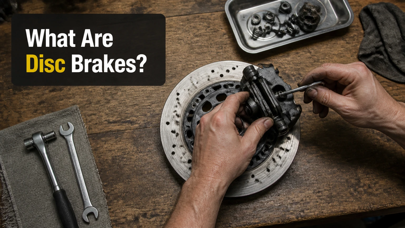
Disc brakes are mechanical friction-based systems that slow or stop a vehicle by pressing heat-resistant friction pads directly against a rotating metal rotor. This high-pressure clamping action converts the kinetic energy of the vehicle into thermal energy, safely dissipating extreme heat into the surrounding atmosphere to bring a moving vehicle to a controlled halt.
Key Facts / At a Glance
- Standard passenger car hydraulic systems generate 300 to 500 PSI of line pressure during normal commuting stops.
- Emergency panic braking can spike hydraulic line pressure well over 1,200 PSI instantly.
- Optimal friction coefficients for daily commuter brake pads range narrowly between 0.35 and 0.45.
- Track-oriented carbon-ceramic braking systems resist thermal degradation at temperatures up to 1,000 degrees Celsius.
- New front friction material layers start at approximately 12mm thick and require mandatory replacement at 2mm.
How Does a Disc Brake System Actually Work?
A disc brake system works by forcing a hydraulically actuated caliper to clamp stationary brake pads against a spinning metal rotor attached directly to the vehicle wheel hub. The entire mechanical advantage relies entirely on Pascal’s Law, which states that pressure exerted anywhere in a confined incompressible fluid is transmitted equally in all directions. This physical principle multiplies the light 20-pound physical force applied by the driver foot into massive, multi-ton clamping pressure at the wheels.
The Five Core Mechanical Components
An advanced hydraulic disc setup contains five primary mechanical elements that must operate in perfect unison. Failure in any single component compromises the entire deceleration network.
- Brake Rotor (Disc): A circular plate typically cast from high-carbon G3000 grade iron. It bolts directly to the wheel hub assembly and spins precisely at the speed of the tire.
- Brake Caliper: A heavy structural housing that straddles the top or leading edge of the rotor. It contains internal fluid channels, pistons, and highly durable EPDM rubber dust boots that protect the pressure seals from road debris.
- Brake Pads: Rigid steel backing plates chemically bonded with a sacrificial high-friction compound material. Engineers tune these compounds using specialized chamfers and shims to eliminate high-frequency vibrations.
- Brake Pistons: Cylindrical metal or phenolic resin plugs located inside the caliper housing. They slide outward when subjected to internal hydraulic pressure and retract slightly when pressure drops.
- Master Cylinder: The primary hydraulic pump attached directly to the engine firewall. It features a sealed reservoir of hygroscopic brake fluid and pressurizes the external steel lines when the driver depresses the pedal.
Step-by-Step Actuation Sequence
The complete physical sequence of a brake application executes through six precise mechanical steps, transforming driver intent into massive thermal energy within fractions of a second.
- Pedal Input: The operator depresses the foot pedal, which utilizes a mechanical lever arm to push the master cylinder internal pushrod forward.
- Hydraulic Pressurization: The master cylinder primary piston forces specialized brake fluid (typically glycol-based DOT 3, DOT 4, or DOT 5.1) through rigid steel chassis lines and flexible reinforced rubber hoses.
- Piston Extension: Pressurized fluid enters the sealed caliper chamber behind the pistons, forcibly displacing the internal pistons outward toward the rotor face.
- Pad Engagement: The advancing pistons push the inner friction material hard against the inner surface of the spinning iron rotor.
- Caliper Reaction: In standard floating configurations, this initial inner contact pushes the entire caliper body inward along its greased guide pins, forcefully pulling the outer pad tightly against the opposite exterior face.
- Thermal Conversion: Continuous bi-lateral clamping pressure generates extreme friction, instantly transforming the forward kinetic momentum of the 4,000-pound vehicle into intense heat energy that rapidly sheds into the passing ambient air.
What Are the Main Types of Calipers and Rotors?
The main types of calipers are categorized strictly by their mounting mechanism (floating or fixed), while rotors are defined by their internal thermal management architecture (solid, vented, drilled, slotted, or composite). Automotive manufacturers specify these hardware designs based heavily on gross vehicle weight, intended top speeds, and mass-production manufacturing budgets.
Caliper Configurations: Floating vs. Fixed
Floating (sliding) calipers utilize one or two fluid pistons located solely on the inboard side of the rotor. The entire heavy cast-iron housing slides laterally on lubricated steel pins to pull the outboard pad inward. This design is highly compact, lightweight, and economical. It serves as standard factory equipment on roughly 80 percent of global passenger vehicles ranging from compact hatchbacks to light-duty pickup trucks.
Fixed calipers feature a completely rigid, non-moving aluminum or steel housing firmly bolted to the suspension knuckle. Pistons sit on both sides of the rotor, arranged in perfectly opposing pairs (ranging from two to eight total individual cylinders). This configuration delivers highly uniform clamping force distribution, superior heat rejection, and perfectly crisp pedal modulation feedback. Fixed calipers are mandatory hardware for high-performance sports cars, armored vehicles, and heavy-duty towing applications where sliding pin deflection would cause catastrophic failure.
Rotor Engineering Options
Solid (plain) rotors consist of a single, continuous disc of precision-machined cast iron. They offer maximum physical surface area and structural integrity for their specific diameter. Automotive engineers specify solid rotors primarily for small, lightweight economy cars or rear axles where total braking thermal loads remain low.
Vented (ventilated) rotors feature internal cooling fins or directional pillars sandwiched strategically between two separate friction faces. These internal vanes act exactly like a centrifugal fan, actively pumping air outward from the center hub to the outer edge as the wheel spins. This active airflow significantly reduces heat build-up on heavy front axles during repeated deceleration cycles.
Drilled and slotted rotors feature precise cross-drilled holes for rapid gas escape and machined surface slots to aggressively scrape away water, brake dust, and road debris. This aggressive surface management maintains an optimal pad contact patch under wet weather or extreme spirited driving conditions, preventing a dangerous phenomenon known as pad hydroplaning.
Carbon-ceramic rotors utilize a highly advanced carbon-fiber-reinforced silicon carbide matrix (C/SiC). This aerospace-grade material reduces unsprung suspension weight by up to 50 percent compared to traditional iron components and completely resists thermal fading up to 1,000 degrees Celsius. These rotors appear exclusively on ultra-high-end supercars and dedicated track racing vehicles due to their immense production costs, which often exceed $10,000 per set.
How Do Brake Pad Compounds Differ?
Brake pad compounds differ fundamentally based on their chemical ratio of organic materials, metallic fibers, and ceramic particles. This ratio directly dictates the exact friction coefficient, maximum operating temperature limit, and rotor wear rate. Selecting the correct pad material requires matching the friction compound chemistry strictly to the operational environment of the vehicle.
Organic pads (Non-Asbestos Organic) utilize rubber, glass, and Kevlar bound tightly by high-heat resins. They are completely silent and highly inexpensive, but they wear away rapidly and lose effectiveness under heavy towing or racing loads.
Semi-metallic pads contain 30 to 65 percent chopped steel, copper, or brass wool mixed with friction modifiers. They offer phenomenal heat conduction and massive initial bite force, making them ideal for heavy trucks. However, they generate significant dark, corrosive brake dust and routinely produce minor squealing noises when operated below optimal temperatures.
Ceramic pads utilize dense ceramic fibers heavily infused with varying percentages of copper strands. They produce almost zero visible light-colored dust, eliminate cold-weather squeal entirely, and maximize both pad and rotor longevity. They represent the premium upgrade standard for modern luxury vehicles and daily commuters.
| Compound Type | Optimal Friction Coefficient | Rotor Wear Rate | Primary Target Application |
|---|---|---|---|
| Non-Asbestos Organic (NAO) | 0.30 to 0.35 | Low | Lightweight urban commuter cars. |
| Semi-Metallic | 0.40 to 0.55 | High | Heavy towing trucks and track vehicles. |
| Ceramic | 0.35 to 0.45 | Very Low | Luxury vehicles and premium daily drivers. |
| Carbon-Matrix | 0.50 to 0.65 | Extremely High | Professional motorsport racing only. |
Engineering Comparison: Disc Brakes vs. Drum Brakes
Disc brakes massively outperform drum brakes in high-speed heat dissipation, severe fade resistance, and immediate wet weather recovery, while drum brakes offer lower manufacturing costs and far simpler mechanical parking brake integration. Automotive manufacturers systematically transitioned front axles to disc systems in the 1970s because the front wheels handle 70 percent of a vehicle stopping load during weight transfer. This physics reality left inferior drum brakes acceptable only for the rear axles on strict budget-class vehicles.
While undeniably superior in kinetic energy conversion, disc systems possess specific mechanical limitations. They remain completely exposed to the elements, making them highly vulnerable to environmental corrosion when a vehicle sits idle outdoors for extended periods. Furthermore, integrating a mechanical emergency parking brake into a rear disc caliper requires complex, failure-prone internal ratcheting mechanisms. By contrast, rear drums handle the parking brake task effortlessly with simple, robust cable-pulled levers expanding the internal shoes.
| Evaluation Parameter | Disc Brake Systems | Drum Brake Systems |
|---|---|---|
| Heat Dissipation Efficiency | Open air exposure allows immediate, rapid cooling. | Heat remains completely trapped inside the heavy iron drum housing. |
| Brake Fade Resistance | Maintains mechanical friction performance consistently when hot. | Fades rapidly under repetitive high-speed stops due to heat saturation. |
| Wet Weather Recovery | Centrifugal force flings water off the spinning disc instantly. | Water can pool and remain trapped inside the enclosed bottom drum lip. |
| Mechanical Maintenance | Simple visual inspection of highly visible pads and fast bolt-on swaps. | Complex multi-spring return linkages and enclosed tensioned shoes. |
| Parking Brake Integration | Requires expensive internal ratcheting caliper mechanisms. | Built-in mechanical shoe expansion is simple, cheap, and highly robust. |
What Are the Critical Operating Metrics and Financial Costs?
Disc brake systems operate under extreme physical constraints, commonly reaching hydraulic fluid pressures of 1,200 PSI and rotor face temperatures well exceeding 350 degrees Celsius during a standard highway panic stop. Understanding these physical thresholds and the associated financial maintenance costs ensures proper vehicle safety and accurate repair budget planning.
Thermal and Hydraulic Operating Envelopes
Standard street pad compounds operate most efficiently between a 0.35 and 0.45 mathematical friction coefficient. The thermal envelope for a standard passenger car brake system functions safely between 35 and 350 degrees Celsius. In stark contrast, track-focused racing systems require operating base temperatures of up to 800 degrees Celsius just to reach their optimal 0.50 to 0.62 friction coefficient. If you run a racing pad on a cold city street, the vehicle will struggle to stop safely.
A typical daily commuter stop generates roughly 300 to 500 PSI of internal line pressure. During a sudden emergency ABS-activated stop, the hydraulic pressure instantly spikes well past 1,200 PSI, requiring reinforced braided steel or thick EPDM rubber hoses to prevent lines from bursting outward under the load.
Typical practitioner measurements dictate that brand new front brake pad friction layers measure exactly 10mm to 12mm thick straight out of the box. Federal transportation safety guidelines strongly recommend immediate pad replacement when the friction material wears down to a 2mm remaining thickness.
A 2023 technical review of automotive maintenance data by the Car Care Council confirmed that glycol-based DOT 3 and DOT 4 brake fluids absorb 1 to 2 percent of their total weight in atmospheric water moisture every single year. This steady moisture absorption dramatically lowers the fluid boiling point and aggressively corrodes internal ABS pump valves, making routine fluid flushes mandatory for system survival.
Average Replacement Costs and Labor Times
The following figures represent current auto-industry financial averages for standard vehicle classes, reflecting both premium replacement parts and professional shop labor rates at standard independent facilities.
| Vehicle Class | Required Component Service | Financial Cost Range (Parts & Labor) | Estimated Labor Time |
|---|---|---|---|
| Commuter Economy Sedan | Front ceramic pads and solid rotors replacement | $250 to $450 total per axle | 1.0 to 1.5 shop hours |
| Mid-Size SUV or Light Truck | Front semi-metallic pads and vented rotors replacement | $400 to $750 total per axle | 1.5 to 2.0 shop hours |
| High-Performance Sports Car | Big brake kit multi-piston caliper hardware upgrade | $1,500 to $4,500 complete set | 3.0 to 5.0 shop hours |
| All Standard Vehicle Classes | Complete hydraulic brake fluid pressure flush | $90 to $160 total service | 0.5 to 1.0 shop hours |
What Are the Most Common Installation and Maintenance Mistakes?
The most common disc brake installation mistakes include neglecting slider pin lubrication, skipping the thermal pad bedding procedure, and improperly torquing wheel lug nuts with impact guns. These highly specific errors account for the vast majority of premature hardware failures, warped rotors, and frustrating customer noise complaints at professional automotive repair facilities.
Reassembling sliding calipers completely dry or using standard petroleum-based chassis grease destroys the delicate rubber dust boots instantly. This causes the heavy caliper to bind permanently on its metal pins, resulting in severe uneven pad wear where the inner pad vanishes while the outer pad remains brand new. Technicians must always apply high-temperature synthetic silicone brake grease to these specific sliding components.
Failing to perform a rigorous series of controlled slow-downs after installing new parts prevents the chemical compound material from transferring a uniform friction layer onto the raw iron rotor steel. A proper bedding procedure requires executing five moderate stops from 40 mph, followed immediately by five aggressive stops from 60 mph without triggering the ABS, then driving for ten minutes without stopping to cool the system. Skipping this leaves the driver with poor initial pedal bite and localized hard spots on the iron surface.
Tightening wheel lug nuts haphazardly with an uncontrolled pneumatic impact gun applies wildly uneven clamping loads across the rotor hat flange. Once the vehicle is subjected to severe thermal braking cycles, this uneven tension physically causes the rotor to warp into a distinct wave shape. This immediately induces massive steering wheel vibrations known as lateral runout. A calibrated torque wrench set to manufacturer specifications (typically 80 to 100 lb-ft applied in a star pattern) is strictly mandatory.
Finally, forcing caliper pistons back into their bores blindly without opening the bleeder valve pushes contaminated, debris-filled fluid backward through the master cylinder. This backward fluid flow frequently destroys the highly delicate internal valving networks inside modern anti-lock braking system (ABS) modules, turning a $300 brake job into a $2,000 electrical repair.
Diagnostic Troubleshooting Matrix
Identifying hydraulic and mechanical system failures early prevents a catastrophic loss of vehicle control at high speeds. Use this diagnostic matrix to match physical driver symptoms with their required mechanical interventions.
| Observed System Symptom | Root Mechanical Cause | Required Rectification Action |
|---|---|---|
| Spongy, soft, or sinking brake pedal feel | Air bubbles trapped within the fluid lines or degraded, boiling fluid. | Perform a full system fluid flush and manual four-wheel bleed sequence. |
| High-pitched metallic squealing during stops | Sacrificial metal wear indicators actively rubbing the iron rotor face. | Swap in new brake pads and precision-turn or replace the worn rotors entirely. |
| Violent steering wheel shudder under braking | Lateral Disc Thickness Variation (DTV) due to severe localized rotor hot spots. | Measure lateral runout with a dial indicator and replace the affected rotors. |
| Vehicle steering pulls hard to one side | Seized internal caliper piston or completely stuck slider pins on the opposite side. | Rebuild the internal rubber seals or replace the entire defective caliper assembly. |
How Do Modern Innovations Like ABS and EVs Change Disc Brakes?
Modern digital innovations require disc brakes to interface rapidly with complex electronic sensors and manage entirely new usage patterns, transforming them from simple analog hydraulic clamps into computer-managed safety networks. Anti-lock Braking Systems (ABS) actively monitor individual wheel rotational speeds thousands of times per second using magnetic hall-effect sensors. When a sensor detects an impending tire skid on ice or water, the ABS pump instantly takes over, rapidly pulsing hydraulic pressure to that specific caliper up to 15 times per second. This automated modulation allows the driver to maintain full steering control during extreme panic stops.
Electric vehicles (EVs) introduce a highly unique engineering challenge known informally as lot rot or regenerative rust. Because EVs rely heavily on reversing the electric drive motor to slow the vehicle and recapture battery energy, the physical hydraulic disc brakes often go completely unused for weeks at a time. This total lack of physical friction allows severe surface rust to accumulate aggressively on the iron rotors. To combat this deterioration, automotive engineers now program EV software to occasionally apply the physical brake pads lightly without any driver input, specifically to wipe the iron rotors clean and keep the mechanical safety system functional.
Electronic Parking Brakes (EPB) have largely replaced the traditional mechanical hand lever and tensioned steel cable with small, motorized actuators bolted directly to the rear calipers. When the driver pushes a dashboard button, these powerful electric motors physically drive the internal caliper piston outward to lock the rear wheels securely. Technicians now require specialized OBD2 diagnostic scan tools to digitally command these motors to retract into service mode before they can safely perform a routine rear pad replacement.
Frequently Asked Questions (FAQ)
How long do disc brake pads usually last? Standard front brake pads typically last between 30,000 and 50,000 miles under normal urban commuting conditions. Rear pads handle significantly less of the overall stopping load and often survive 60,000 to 80,000 miles. Driving heavily loaded trucks in mountainous terrain can reduce this standard lifespan by more than half.
Why do my brakes squeak first thing in the morning? Morning brake squeak almost always results from a microscopic layer of overnight flash rust accumulating on bare iron rotors due to ambient humidity. The high-pitched noise happens as the abrasive brake pads scrape this temporary rust layer away during your first few stops. If the noise disappears entirely after a mile of driving, the system is functioning perfectly normally.
Should I resurface my rotors or just replace them? Modern passenger car rotors are cast much thinner than vintage components specifically to reduce vehicle weight and improve fuel economy. Once they warp or develop deep concentric grooves, cutting them smoothly on a lathe often drops them dangerously below the minimum safe thickness specification. Replacing them entirely is usually much safer and highly cost-effective.
Can I mix different pad materials on the front and rear? Yes, you can safely run ceramic pads on the front axle to reduce visible brake dust and semi-metallic pads on the rear axle to handle heavy towing loads. However, you must never mix different compound materials on the left and right sides of the exact same axle, as this will immediately cause the vehicle to violently pull toward the side with the higher friction coefficient.
What exactly is brake fade? Brake fade is the sudden, highly dangerous loss of stopping power that occurs when system temperatures radically exceed the chemical limits of the pad compound or the physical boiling point of the hydraulic fluid. The pedal may feel rock hard with zero actual vehicle deceleration, or it may drop straight to the floorboard without engaging the calipers at all.
The Bottom Line: Understanding what are disc brakes requires looking past the simple pedal in the cabin to the precise orchestration of hydraulics, friction chemistry, and thermal management happening at the wheel. By selecting the correct rotor and pad compounds for your specific driving environment and adhering to strict fluid maintenance schedules, you ensure maximum deceleration performance and total vehicle safety under all conditions.