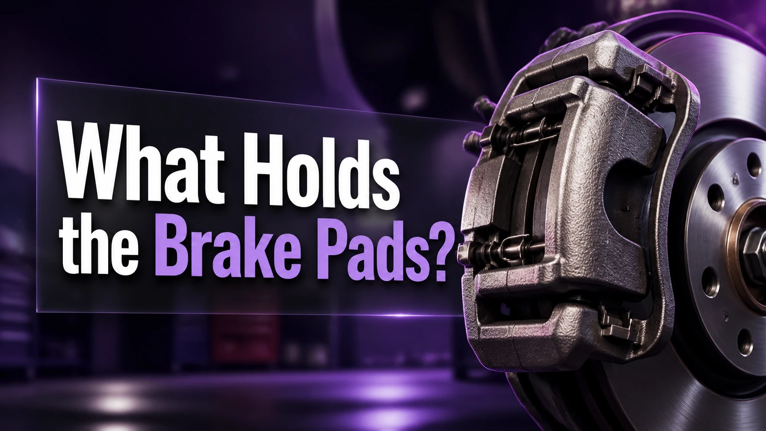
In a disc brake system, the brake caliper is the primary housing that holds the brake pads. The caliper body houses pistons that compress the pads, while the attached caliper bracket, stainless steel abutment clips, guide pins, and retaining pins secure the pads structurally and control their horizontal sliding alignment against the brake rotor.
At a Glance
- The brake caliper and its mounting bracket serve as the primary structural housing holding the brake pads against rotational torque.
- Stainless steel abutment clips line the bracket channels to allow 0.10 mm to 0.15 mm of sliding clearance while dampening pad rattle.
- Floating calipers slide on guide pins with 0.03 mm to 0.08 mm clearance, whereas fixed calipers hold pads using steel retaining pins.
- Square-cut rubber piston seals deform under hydraulic pressure and retract the piston by 0.10 mm to 0.20 mm when the pedal is released.
- Friction material replacement is mandatory at 2.0 mm thickness, though proactive replacement is recommended between 3.0 mm and 4.0 mm.
What Components Make Up the Brake Pad Mounting System?
The system that holds brake pads consists of four primary mechanical elements: the caliper bracket, abutment clips, guide or retaining pins, and the caliper housing itself. Together, these parts isolate the pads, manage thermal expansion, and absorb the massive rotational torque generated when friction material clamps against the spinning brake rotor.
+-----------------------------------------------------------------+
|                         BRAKE CALIPER                           |
|  +-----------------------------------------------------------+  |
|  |                     CALIPER BRACKET                       |  |
|  |  +-----------------------------------------------------+  |  |
|  |  |                 STAINLESS ABUTMENT CLIPS            |  |  |
|  |  |  +-----------------------------------------------+  |  |  |
|  |  |  |                 BRAKE PAD EARS                |  |  |  |
|  |  |  |  [ Friction Material ] ---> [ Brake Rotor ]   |  |  |  |
|  |  |  +-----------------------------------------------+  |  |  |
|  |  +-----------------------------------------------------+  |  |
|  +-----------------------------------------------------------+  |
|            [ Guide Pins / Retaining Pins & Rubber Boots ]       |
+-----------------------------------------------------------------+
In a standard floating caliper setup, the caliper bracket acts as the rigid anchor. Stainless steel abutment clips snap into the bracket channels to provide a low-friction track for the brake pad metal ears. Guide pins pass through rubber dust boots to connect the caliper body to the bracket, allowing lateral sliding movement.
In a fixed caliper setup, the caliper body mounts directly to the steering knuckle without a separate sliding bracket. Instead, rigid steel retaining pins pass through mounting holes punched directly through the top of the brake pad backing plates, locking them laterally within the caliper cavity.
What Is the Role of the Caliper Bracket in Holding Brake Pads?
The caliper bracket is a heavy cast-iron or forged aluminum frame bolted directly to the vehicle steering knuckle or wheel spindle. Its primary mechanical role is to support the physical weight of the brake pads and absorb the extreme rotational shearing forces created during braking.
When the friction material grips the spinning rotor, the rotor attempts to drag the brake pads along with its rotation. The caliper bracket acts as a mechanical stop. The metal ears or tabs on the ends of the brake pad backing plates rest inside reinforced channels cut into the caliper bracket.
By anchoring the pads directly to the vehicle suspension, the bracket prevents the pads from twisting out of alignment or tearing away from the hydraulic assembly. The caliper bracket also keeps the pads precisely parallel to the rotor surface, ensuring uniform wear across the friction face.
What Do Abutment Clips and Hardware Shims Do?
Abutment clips, also known as hardware clips or track inserts, are thin, stamped stainless steel pieces that fit into the sliding channels of the caliper bracket. Their primary job is to create a smooth, rust-resistant surface for the brake pad ears to slide across while dampening operational vibration.
Without abutment clips, the steel backing plates of the brake pads would ride directly against the cast-iron caliper bracket. Over time, friction would carve deep grooves into the soft cast iron, trapping the pads and causing severe drag.
Abutment clips feature tiny tension tabs that apply constant, mild force against the brake pad ears. This spring tension prevents the pads from rattling inside the bracket while allowing them to move forward and back freely during application and release.
How Do Fixed Calipers Hold Brake Pads Differently Than Floating Calipers?
Floating calipers move laterally on sliding pins and use a single bracket to hold the pads, whereas fixed calipers are rigidly mounted and hold the pads inside a rigid central cavity using removable retaining pins and leaf springs.
| Feature | Floating Caliper System | Fixed Caliper System |
|---|---|---|
| Mounting Style | Moves laterally on guide pins | Rigidly bolted to steering knuckle |
| Primary Pad Fastener | Bracket channels with abutment clips | Removable steel retaining pins and cotter pins |
| Piston Configuration | 1 or 2 pistons on inner side only | 4, 6, or 8 opposing pistons (both sides) |
| Anti-Rattle Mechanism | Spring tabs on abutment clips | Cross-shaped top leaf spring |
| Typical Application | Passenger cars, light trucks, everyday commuters | Sports cars, heavy trucks, high-performance racing |
In a floating system, the outer pad is held by the sliding outer frame of the caliper, while the inner pad rests against the hydraulic piston. When hydraulic pressure pushes the piston outward, the entire caliper body pulls inward on its guide pins to clamp the outer pad.
In a fixed system, the caliper body does not move. The pads slide inward and outward along horizontal steel pins that span the top of the caliper cavity. A cross-shaped or bridge-style leaf spring sits over the pins, applying downward pressure against the top of the pad backing plates to eliminate rattle and chatter.
What Clearance Measurements Keep Brake Pads from Seizing or Clunking?
Precision engineering governs the mounting tracks of brake pads. Minor variances measured in tenths of a millimeter dictate whether a braking system operates smoothly or fails catastrophically.
       [ Caliper Bracket Channel ]
       +-------------------------+
       |   Stainless Steel Clip  |
       |  +-------------------+  |
       |  |   Brake Pad Ear   |  |  <--- 0.10 mm to 0.15 mm Clearance
       |  +-------------------+  |       (Tighter = Seizes / Looser = Clunks)
       |   Stainless Steel Clip  |
       +-------------------------+
- Pad Ear Movement Clearance: Brake pads require a physical gap of 0.10 mm to 0.15 mm between the metal ear of the pad and the stainless steel abutment clip. If this clearance drops below 0.10 mm due to corrosion or manufacturing defects, thermal expansion will cause the pad to seize inside the bracket. If clearance exceeds 0.20 mm, the pad will physically slam into the bracket wall when changing rotational direction, producing an audible clunk.
- Slider Pin Play: The clearance between the caliper guide pin and its machined bracket bore ranges tightly between 0.03 mm and 0.08 mm. This tight tolerance maintains strict parallelism between the pad and rotor while allowing effortless axial movement. Excessive bore wear beyond 0.12 mm allows the caliper to tilt under load, causing tapered pad wear.
How Far Does a Caliper Piston Retract to Release the Brake Pad?
When you release the brake pedal, the caliper piston retracts by a microscopic distance of 0.10 mm to 0.20 mm. This tiny clearance disengages the friction material from the spinning rotor without wasting pedal movement during the next brake application.
The mechanical force behind this retraction is not a spring, but a specialized rubber ring called a square-cut piston seal. This elastomeric seal sits inside a grooved channel along the inner wall of the caliper hydraulic cylinder.
[ BRAKE PEDAL APPLIED ]                  [ BRAKE PEDAL RELEASED ]

  Hydraulic Pressure                       Seal Restores Shape
        =====>                                   <=====
+-------+  +---------+                   +-------+  +---------+
| Caliper  | Piston  |                   | Caliper  | Piston  |
| Wall  ///|=======> |                   | Wall  \\\| <====== |
+-------+  +---------+                   +-------+  +---------+
      Square-Cut Seal                           Square-Cut Seal
    (Deforms Forward)                        (Pulls Piston Back)
When hydraulic fluid fills the caliper chamber, it forces the piston forward. As the piston slides, it grips the inner ring of the square-cut seal, twisting the rubber profile into a slight trapezoid shape.
The moment hydraulic pressure drops when you lift your foot off the pedal, the deformed rubber seal snaps back to its natural square shape. This elastic action pulls the piston back roughly 0.15 mm, relieving clamping force and letting the brake pads float away from the rotor.
What Is the Minimum Safe Thickness for Brake Pads Before Replacement?
Brand-new automotive brake pads typically feature between 10.0 mm and 12.0 mm of usable friction material bonded to a 5.0 mm thick steel backing plate. The absolute safety and legal threshold for mandatory replacement is 2.0 mm of remaining friction layer.
[ NEW PAD ]          10.0 mm - 12.0 mm  =========================== (Optimal)
[ CAUTION ]           3.0 mm - 4.0 mm   =================== (Schedule Service)
[ REPLACE NOW ]       2.0 mm            ========== (Legal Minimum / Nickel Thickness)
[ CRITICAL FAILURE ]  0.0 mm            === (Metal-on-Metal / Rotor Destruction)
Driving on friction material below 2.0 mm creates severe risks. At 2.0 mm, roughly the thickness of a US nickel, the thermal dissipation capacity of the pad drops dramatically, increasing the likelihood of fluid boil and sudden pedal fade.
Most professional automotive technicians recommend replacing brake pads when friction material wears down to between 3.0 mm and 4.0 mm. Replacing pads at this stage ensures a safety margin, prevents wear indicators from scarring the rotor, and keeps localized heat away from internal caliper rubber seals.
What Holds Friction Material in Drum Brakes Instead of Brake Pads?
Drum brake systems do not use brake pads, calipers, or sliding brackets; instead, they use curved friction assemblies called brake shoes held against a stationary backing plate by a network of heavy steel springs and retention pins.
                  +----------------------------+
                  |    DRUM BRAKE ASSEMBLY     |
                  +----------------------------+
                                |
        +-----------------------+-----------------------+
        |                                               |
  [ Hold-Down Pins & Springs ]                 [ Return Springs ]
  Hold shoes flat against                     Pull shoes inward away
  the stationary backing plate.               from drum after braking.
        |                                               |
        +-----------------------+-----------------------+
                                |
                    [ Star Wheel Adjuster ]
                    Maintains shoe-to-drum distance
                    as friction material wears.
Brake shoes are crescent-shaped metal structures lined with friction material. They sit entirely inside a hollow metal drum that rotates with the vehicle wheel. The component network holding drum brake shoes includes:
- Hold-Down Pins and Springs: Small steel pins pass through holes in the backing plate and through the center of the brake shoes. Metal cup washers and spring coils lock over the pin tips, holding the shoes flat against the backing plate while permitting radial sliding.
- Return Springs: Heavy duty extension springs span the gap between the top and bottom tips of the two opposing shoes. These springs exert powerful tension to pull the shoes away from the inner drum surface the instant hydraulic pressure drops inside the wheel cylinder.
- Star Wheel Adjuster: A threaded screw mechanism positioned at the bottom of the shoes that sets the rest distance between friction linings and the drum wall as the material wears.
How Does an Electronic Parking Brake (EPB) Lock Rear Brake Pads?
An Electronic Parking Brake (EPB) uses a high-torque electric motor bolted directly to the back of the rear caliper body to mechanically drive the hydraulic piston forward, pressing the brake pads against the rotor without requiring hydraulic pressure.
When you toggle the EPB switch inside the vehicle cabin, a control unit sends electrical current to the integrated caliper motor. The motor turns a compact planetary gear set, which rotates a threaded spindle shaft inside the hollow center of the caliper piston.
As the spindle shaft rotates, it drives an internal nut forward against the inner face of the piston crown. This mechanical movement pushes the piston outward, clamping the brake pads tightly against the rotor. Because the screw thread is non-reversing, the piston remains locked in place even if vehicle battery power is disconnected.
Why Do Frozen Guide Pins Cause Uneven Inner and Outer Brake Pad Wear?
When a rubber dust boot on a floating caliper pin tears, water and road salt penetrate the guide bore, washing away synthetic silicone lubricant and corroding the steel pin solid.
[ FROZEN GUIDE PIN MECHANISM ]

Step 1: Water/Salt enters via torn boot  ---> Corrodes steel slider pin.
Step 2: Caliper body freezes in place   ---> Cannot slide laterally.
Step 3: Brake pedal pressed             ---> Inner piston pushes Inner Pad (WEARS FAST).
                                             Outer Caliper cannot pull Outer Pad (NO WEAR).
Result: Inner pad wears down to bare metal; Outer pad looks brand new.
When a guide pin freezes, the caliper body loses its ability to slide laterally. When the driver depresses the brake pedal, the hydraulic piston successfully pushes the inner pad against the inner rotor face. However, because the caliper frame cannot slide backward along the frozen pin, it fails to pull the outer pad against the outer rotor face.
This failure mode focuses 100% of the braking force and thermal stress onto the inner pad. Consequently, the inner pad wears down to its metal backing plate in a matter of weeks, while the outer pad remains virtually untouched.
What Is Bracket Rust Jacking and How Does It Freeze Brake Pads?
Rust jacking occurs when moisture seeps underneath the stainless steel abutment clips, causing the underlying cast-iron caliper bracket to corrode and expand. As iron oxide forms, its volume expands up to six times larger than the original metal, creating intense pressure against the underside of the stainless clip.
[ CAST IRON BRACKET ]  --->  Corrodes & Expands  --->  [ RUST JACKING FORCE ]
                                                               |
                                                               v
[ STAINLESS CLIP ]     <------------------------------- Crushes Track
                                                               |
                                                               v
[ BRAKE PAD EAR ]      <------------------------------- PINCHED SOLID!
                                                 (Stuck in Applied Position)
This structural expansion pushes the stainless steel clip outward, crushing the clearance track designed for the brake pad tabs. The expanding rust pinches the pad ears tightly, trapping the brake pad in an applied position against the rotor face even after the pedal is released.
Trapped pads generate friction, dragging against the spinning rotor continuously. Within miles, this leads to overheating, acrid smoke, severe rotor warping, fluid boiling, and a total failure of fuel efficiency.
What Happens If Brake Pads Are Installed Backwards or Inverted?
Installing brake pads backwards or swapping asymmetrical inner and outer pads causes immediate mechanical binding, severe noise, and catastrophic loss of braking efficiency.
- Backwards Installation (Friction Facing Away from Rotor): If a pad is flipped so its steel backing plate contacts the rotor, applying the brakes causes raw steel-on-steel friction. Brake force drops by over 70%, throwing metal shavings into the wheel assembly and grinding deep gouges into the rotor surface within seconds.
- Inverted / Swapped Pad Placement: Many modern vehicles use asymmetrical brake pad backing plates featuring directional arrows, specific wear indicator locations, or built-in piston retaining clips on the inner pad only. Forcing an inner pad into an outer bracket channel forces the caliper structure to tilt. This misalignment binds the caliper frame against the pad backing plate, locking the wheel or preventing the piston from applying force.
Why Do New Brake Pads Click or Clunk When Shifting Between Drive and Reverse?
A clicking or clunking noise when changing directions and applying the brakes is caused by excess movement clearance between the brake pad ears and the caliper bracket abutment channels.
Direction Shift: [ REVERSE ]  --->  [ DRIVE ]
                                      |
Brake Applied:                        v
                        Pad shifts forward in track
                                      |
Impact Point:                         v
             [ Pad Ear ]  ==== SLAMS ====>  [ Bracket Wall ]
                                      |
Result:                               v
                            * AUDIBLE CLUNK *
               (Fix: Replace worn clips & apply brake grease)
When a driver switches from reverse to drive and steps on the pedal, the spinning rotor grips the pad and shifts it forward inside the bracket channel. If the anti-rattle clips are worn out, missing spring tension, or if the replacement pad backing plate was manufactured slightly undersized, the pad ear slams against the iron bracket wall, emitting a sharp metal-on-metal clunk.
Installing fresh, high-quality stainless steel hardware clips and applying a thin film of high-temperature synthetic brake grease to the clip sliding surfaces restores proper tension and silences shifting noises.
Should You Reuse Old Hardware Clips When Replacing Brake Pads?
Reusing old stainless steel hardware clips during a brake job is strongly discouraged by master technicians and brake manufacturers.
Over tens of thousands of miles, hardware clips endure severe thermal cycling, fluctuating from ambient air temperatures up to 500 degrees Fahrenheit or higher. Heat degrades the spring temper of the stainless steel, leaving the clips relaxed and unable to apply anti-rattle tension.
Furthermore, road dirt, metallic brake dust, and microscopic rust build up on the clip surfaces, creating a rough, pitted texture. Installing smooth new pads over pitted old clips leads to pad drag, accelerated wear, and premature braking noise. Replacing hardware clips with every pad change ensures clean sliding tracks and quiet operation.
Do Hydraulic Caliper Pistons Physically Hold Brake Pads in Place?
No, caliper pistons do not hold or support brake pads structurally. The pistons act strictly as hydraulic actuators designed to push the pads forward against the rotor face.
The physical weight of the brake pads, along with the immense rotational shear force generated during braking, is held entirely by the caliper bracket or retaining pins.
On the inner pad of many floating caliper systems, a small three-pronged metal spring clip is attached to the metal backing plate. This clip snaps directly into the hollow inner cavity of the caliper piston. However, its purpose is not to bear load; it holds the pad flat against the piston face so the pad retracts evenly when hydraulic pressure drops.
What How-To Steps and Torque Specs Preserve Brake Pad Holding Hardware?
To ensure the hardware holding your brake pads operates without seizing or rattling, execute the installation using the following mechanical procedure and specifications:
- Clean the Bracket Channels: Remove old abutment clips. Use a stiff wire brush and brake cleaner to scrub away iron oxide and dirt from the caliper bracket mounting channels until clean, smooth metal is exposed.
- Apply Corrosion Barrier: Brush a microscopic coat of high-temperature synthetic brake lubricant or ceramic grease onto the bare cast-iron bracket channels before installing new stainless steel clips. This prevents moisture from entering and stops future rust jacking.
- Install New Abutment Clips: Press fresh stainless steel clips firmly into the bracket channels until they snap flush into place. Do not bend or deform the spring tabs during installation.
- Lubricate Pad Sliding Ears: Apply a light film of high-temperature grease directly to the sliding ears of the brake pad backing plates. Keep lubricant strictly away from the friction material and rotor face.
- Service Guide Pins: Pull slider pins from the bracket, wipe clean of old lubricant, inspect rubber boots for tears, and apply a fresh coat of silicone-based brake pin grease. Torque caliper slide pin bolts to 25 to 35 ft-lbs (34 to 47 Nm), depending on manufacturer specifications. Torque caliper bracket-to-knuckle bolts to 80 to 110 ft-lbs (108 to 149 Nm).
The Bottom Line
The brake caliper and its supporting bracket serve as the central anchor that holds brake pads securely against the rotational force of the wheel. While the hydraulic piston applies forward pressure, an ecosystem of stainless steel abutment clips, guide pins, and retaining springs maintains precision clearances ranging between 0.10 mm and 0.15 mm to keep pads sliding smoothly.
Preventing brake failures requires looking beyond basic pad wear; hardware components like guide pins and bracket tracks must be cleaned, lubricated, and replaced regularly. Replacing abutment hardware with every brake job prevents issues like rust jacking and pin freezing, keeping your braking system safe, responsive, and noise-free.